|
|
Testing
Production receiver field testing
Beam measurements
P-band Sensitivity
Polarization characteristics (TBA)
Receiver Log
Production receiver lab testing
Feed Impedance
Feed cross polarization
Prototype receiver field testing
Overall report
Beam measurements (2-band & P-band)
Polarization characteristics
Feed impedance
Prototype receiver lab testing
RFI impact
Data Inventory
Production Receiver Field Testing
Beam Measurements
Holography report for
2-band and
P-band
(07/06)
Sensitivity
report on system sensitivity at P-band when the VHF system is installed and at
2-band
(7/06)
Receiver Log
| Receiver Log |
| Ant |
Pband |
RX |
Type |
Current* |
LMR300 loss |
190/193/195 MHz |
Trx $$ |
Feed Rot** |
Cable Path*** |
Notes |
| |
Ass'y |
Box |
|
P 2 |
Path A |
Path B |
A B |
A B |
Rotation |
|
| (-) |
(-) |
(-) |
(-) |
(A) (A) |
(dB) |
(dB) |
(K) (K) |
(-) (-) |
(-) (-) |
(-) |
| 1 |
tube |
|
|
|
|
|
|
|
|
|
| 2 |
solid |
|
|
|
|
|
|
|
|
|
| 3 |
tube |
|
|
|
|
|
|
|
|
|
| 4 |
solid |
|
|
|
|
|
|
|
|
|
| 5 |
tube |
|
|
|
|
|
|
|
|
|
| 6 |
tube |
|
|
|
|
|
|
|
|
|
| 7 |
tube |
|
|
|
|
|
|
|
|
|
| 8 |
tube |
3 |
GEN-III 50K |
|
|
|
|
|
|
Barrel polz swapped at 2-band RX output. P-band cabling counters swap. |
| 9 |
tube |
8 |
GEN-I 60K |
|
-0.15 |
-0.15 |
64 62 |
Dwn Lft |
Right |
1" cable ext. in barrel. Missing cable stays. 1 nylon screw. |
| 10 |
tube |
|
|
|
|
|
|
|
|
|
| 11 |
tube |
|
|
|
|
|
|
|
|
|
| 12 |
tube |
|
|
|
|
|
|
|
|
|
| 13 |
solid |
|
|
|
|
|
|
|
|
|
| 14 |
tube |
|
|
|
|
|
|
|
|
|
| 15 |
tube |
|
|
|
|
|
|
|
|
|
| 16 |
tube |
|
|
|
|
|
|
|
|
|
| 17 |
tube |
2? |
GEN-III 50K |
|
|
|
|
|
|
|
| 18 |
tube |
|
|
|
|
|
|
|
|
|
| 19 |
tube |
4 |
GEN-III 40K |
1.01 1.40 |
0.142/151/155 |
0.138/149/152 |
41 37 |
Rgt Up |
Bottom |
Barrel polz swapped. To be fixed 1/24. |
| 20 |
tube |
|
|
|
|
|
|
|
|
|
| 21 |
tube |
|
|
|
|
|
|
|
|
|
| 22 |
solid |
|
|
|
|
|
|
|
|
|
| 23 |
solid |
|
|
|
|
|
|
|
|
|
| 24 |
solid |
|
|
|
|
|
|
|
|
|
| 25 |
tube |
|
|
|
|
|
|
|
|
|
| 26 |
tube |
1? |
GEN-III 50K |
0.13 |
|
|
|
|
|
|
| 27 |
solid |
|
|
|
|
|
|
|
|
|
| 28 |
tube |
|
|
|
|
|
|
|
|
|
| Table Notes: |
| (*) Receiver current draw measured in vertex cabin. |
| (**) Orientation (Rgt, Left, Up, Down) are defined looking at the front surface of the subreflector. |
(***) Orientation (Left, Bottom, Right, Top) of hex head cable feed-throughs when looking down inside the barrel cagin, w/r to the receiver mounting plate. For example:
Bottom = P | /------\ Right = P | /------\
L | / x o \ L | / o o \
A | | :: | A | | :: |
T | | x o | T | | x x |
E | \____/ E | \____/
|
| ($) Gen-I prototype refittedinto production standard weather tight box with appropriate control electronics. Production standard 8-pole BPF added between gain stages 1 and 2 [i.e., LNA-quad-BPF-postamp...]. 5K penalty. |
| ($$) Receiver temperature measured in the lab at 195/2 MHx, except for reciever boxes 4 and 8 (200/16 MHz). These included pwer meter measurements 18-24 dB and 7-11 dB above the power head floor (ambient = 18C; cold = 76K). |
Feed Impedance (Production/Lab)
Feed optimization involves adjustment of dipole length and balun L/C parameters,
which depend on clamp length, governing the distance between 2-band and P-band dipoles.
A ~ 1:1 mockup of the asymmetric subreflector and spare VLA and SAO feeds were used to
measure complex impedance at the balun output. Calibration of the balun enabled
solution for the dipole alone. Three clamp and dipole lengths were used.
Report on balun and dipole optimization
(11/01)


Receiver Testing (Production/Lab)
Check List
Feed Cross Polarization (Production/Lab)

Balun cross polarization
Optimization and Testing of Production Dipole Feeds
Impedance measurements for dipoles 1 & 2 attached to balun #4 Impedances for dipoles 1 & 2 (sans balun) are comparable, as expected. Performance below 200 MHz is independent of feed rotation. Improved inductor design 2.
Impedance measurements for dipoles 1 & 2 attached to balun #1Impedances for dipoles 1 & 2 (sans balun) are comparable though less so. Inductor design 1.
Impedance measurements on balun #3 (compared to balun #4)Impedances for dipoles 1 & 2 (sans balun) are comparable, as expected. Improved inductor design 2.
Comparison of calibration factors 1-6 for baluns #3 and #4 Test of calibration stability. Factors for the two baluns should be the same.
Optimization of dipole length and corresponding resistance (for X = 0)
Field testing report (Prototype)
(pdf)
Beam Measurements
Cumulative record of 2-band holography
Cumulative record of P-band holography
Holography report for 2-band and P-band (08/05).
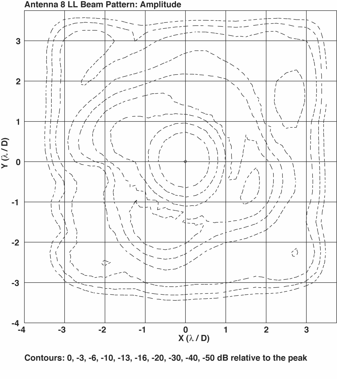
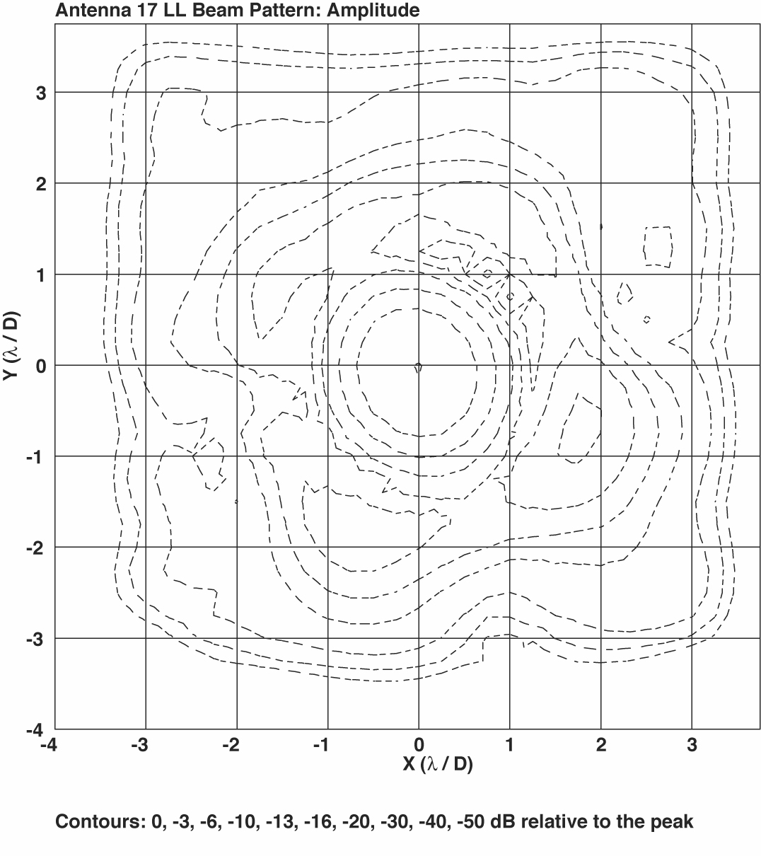
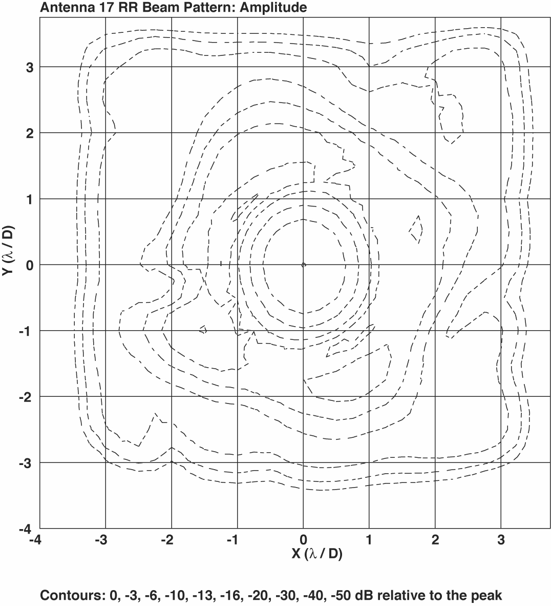
2-band Beam patterns 06/05 (amplitude):
Antenna 8 (LCP)
(RCP)
Antenna 17 (LCP)
(RCP)
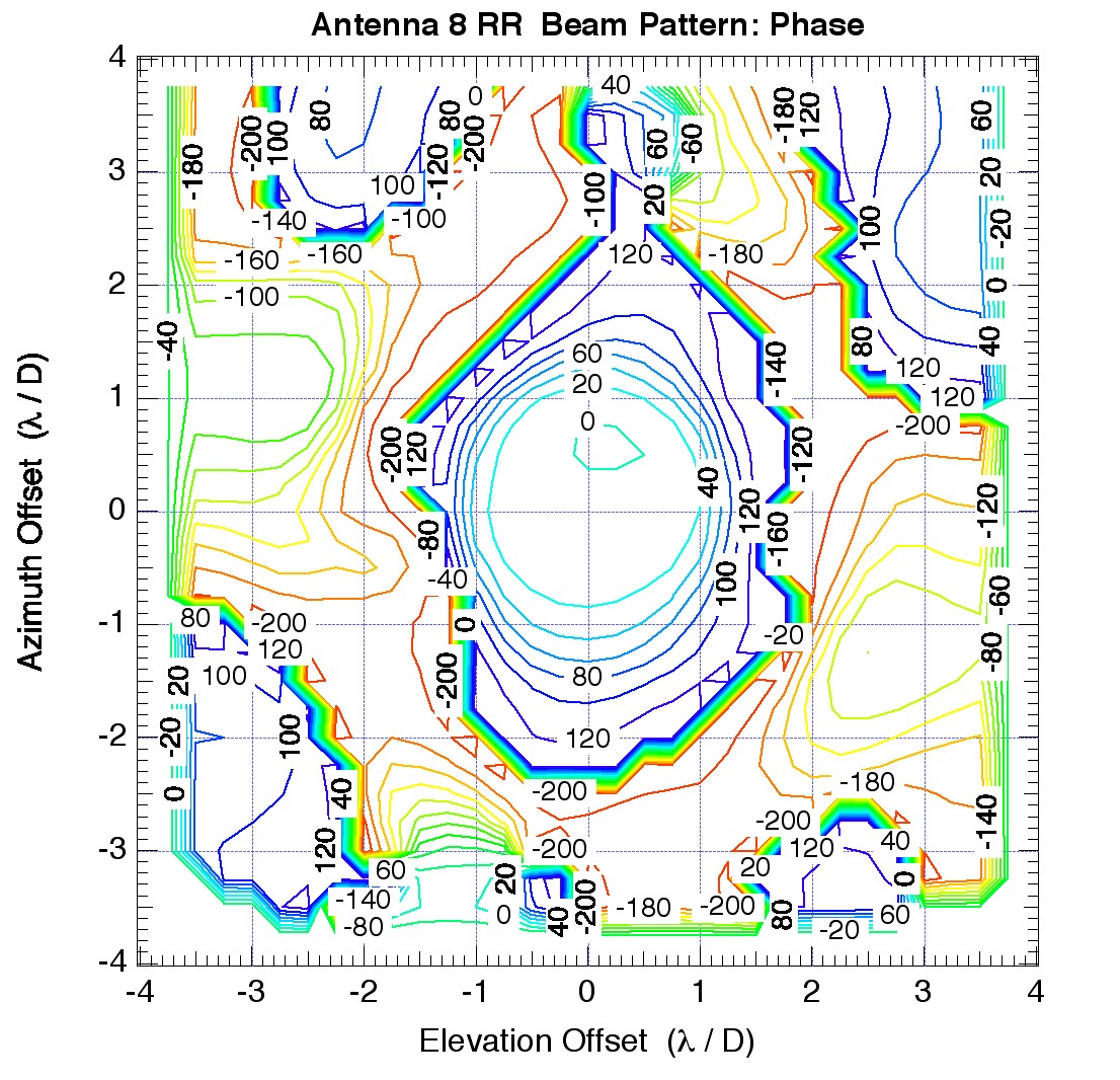
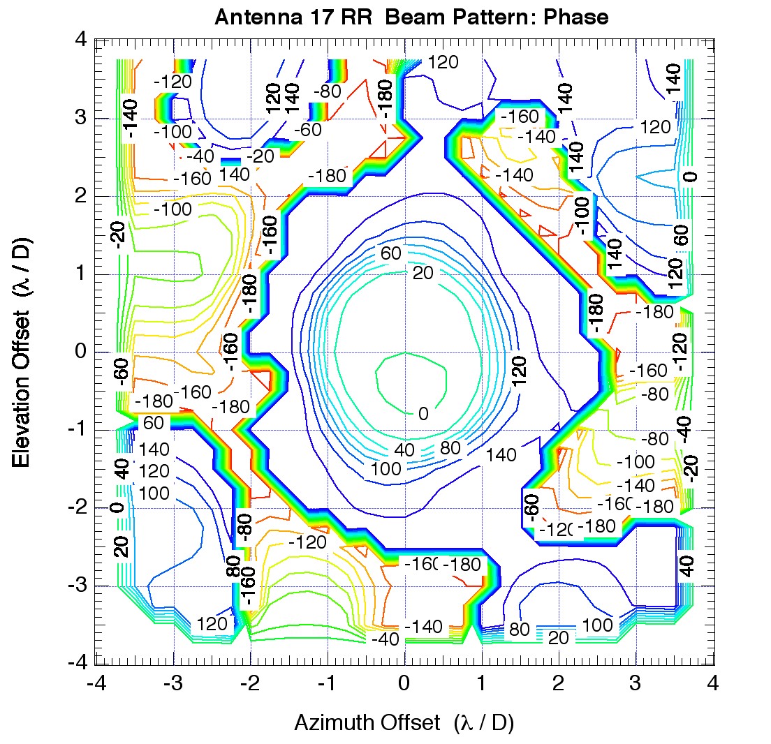
2-band Beam patterns 06/05 (phase):
Antenna 8 (LCP)
(RCP)
Antenna 17 (RCP)
Focus measurements
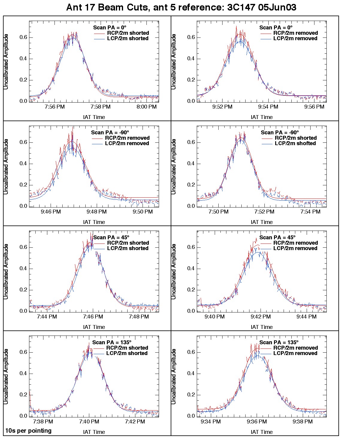
Demonstration of good P-Band performance in presence of shorted 2m dipole.
Beamcuts (06/05)
Results of analysis (06/05)
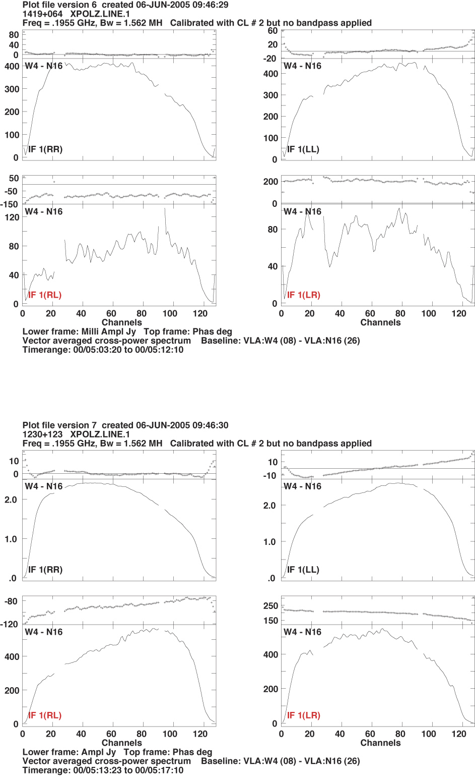
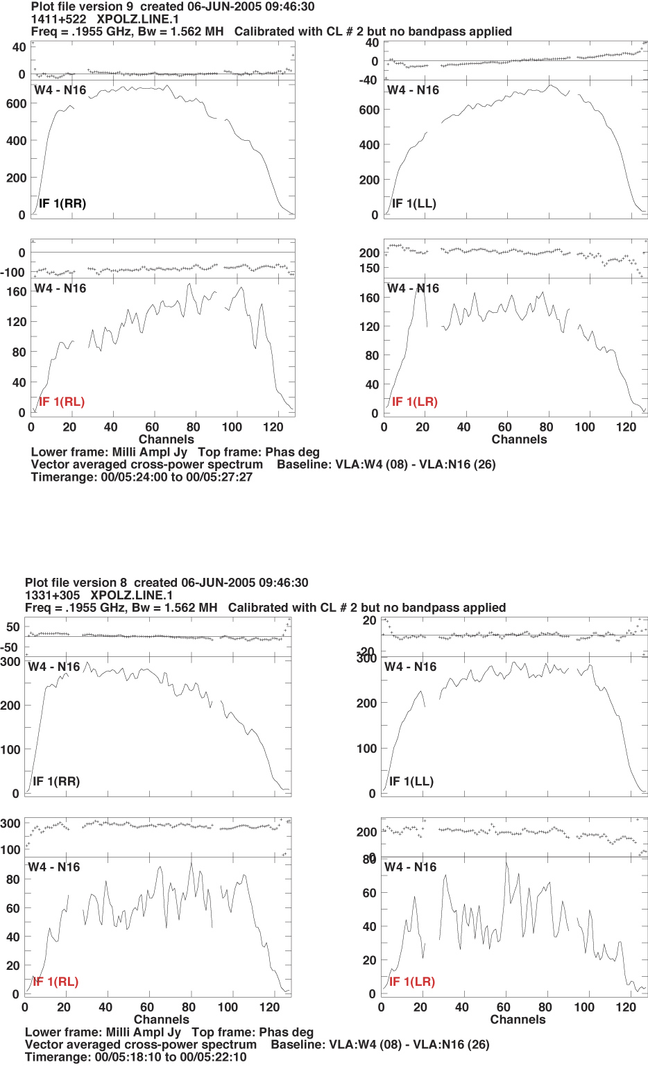
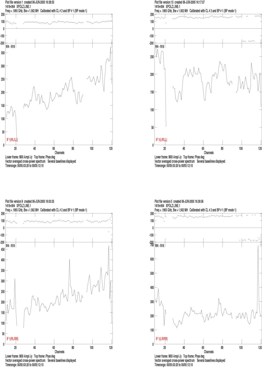
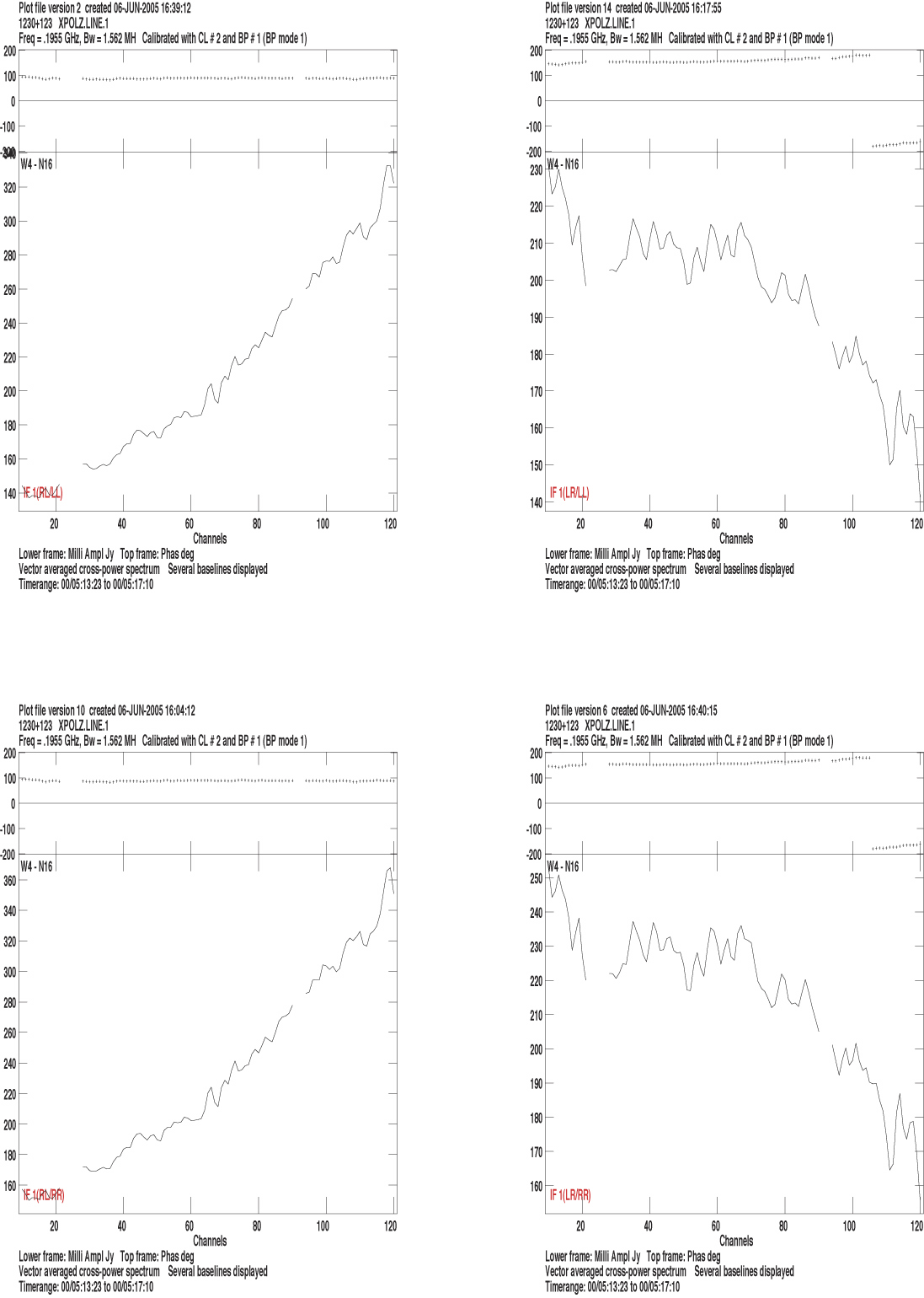
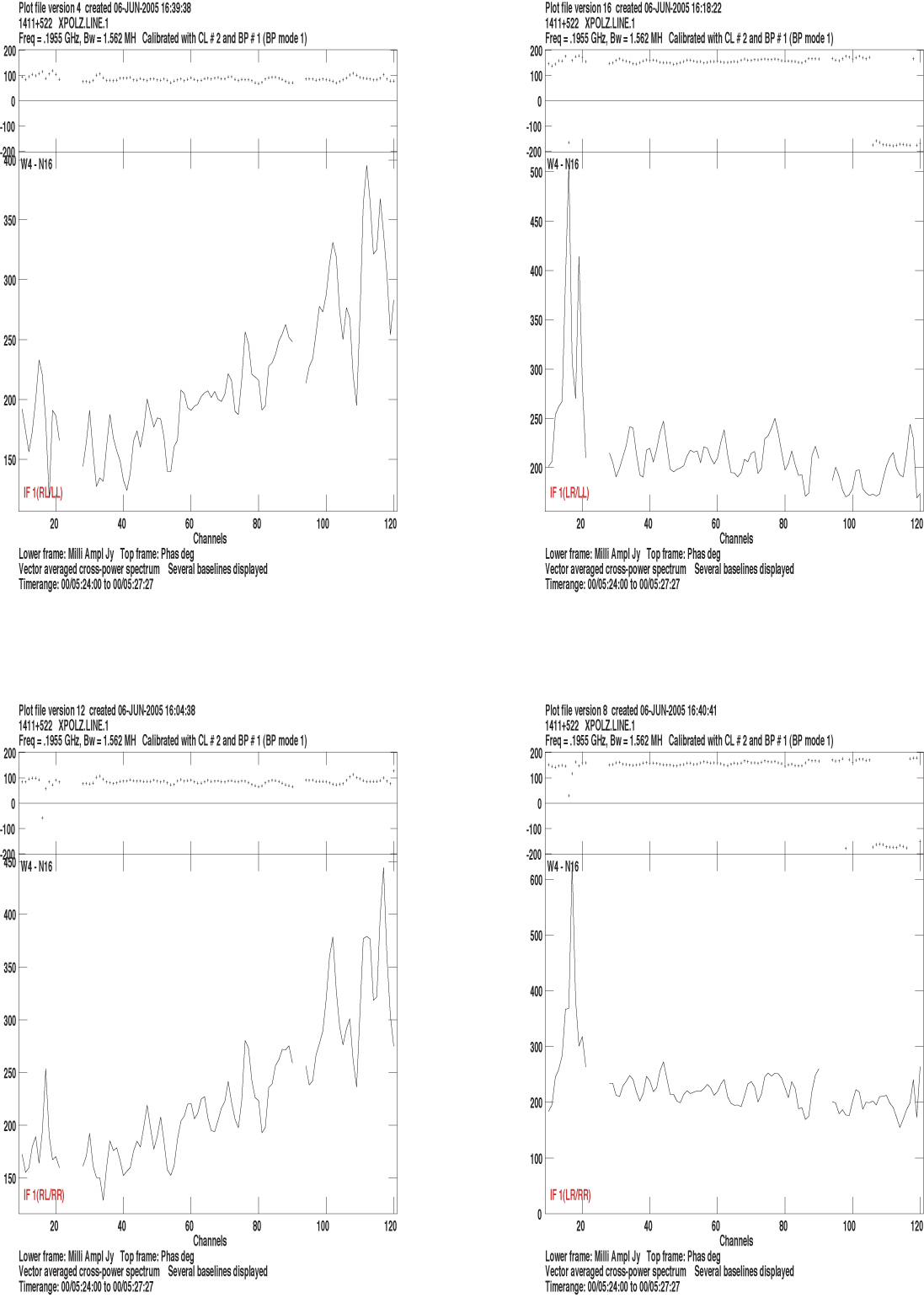
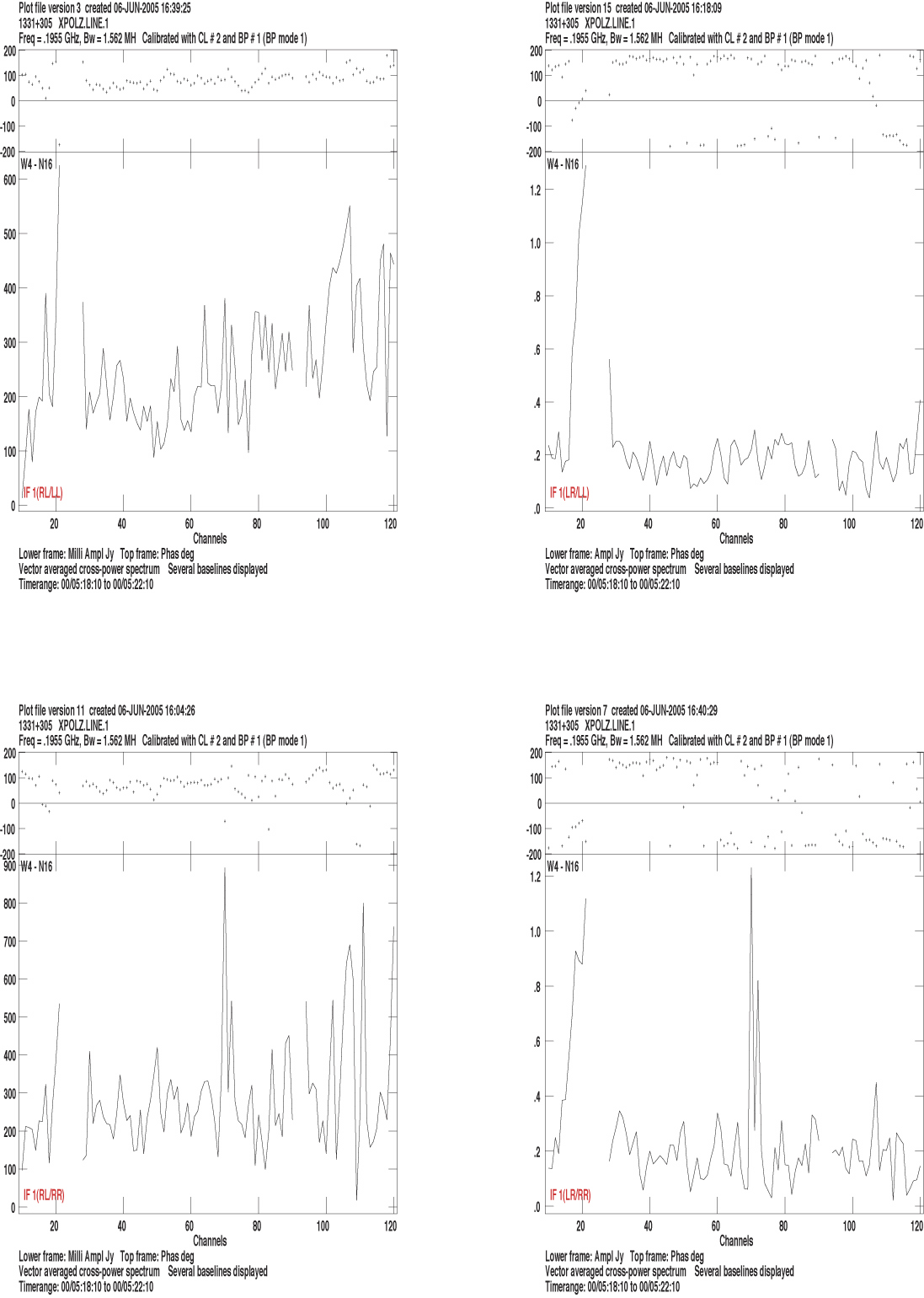
Polarization Response
Demonstration of ~20% polarization leakage
RR, LL, RL, LR fringes at 195.4/1 MHz for VAMP3 (ant 8) and VAMP4 (ant 26)
1419+064 and 1230+123
(05Jun02)
1411+522 and 1331+305 (05Jun02)
1419+064 phase and bandpass calibrated (05Jun02)
1230+123 phase and bandpass calibrated (05Jun02)
1411+522 phase and bandpass calibrated (05Jun02)
1331+305 phase and bandpass calibrated(05Jun02)
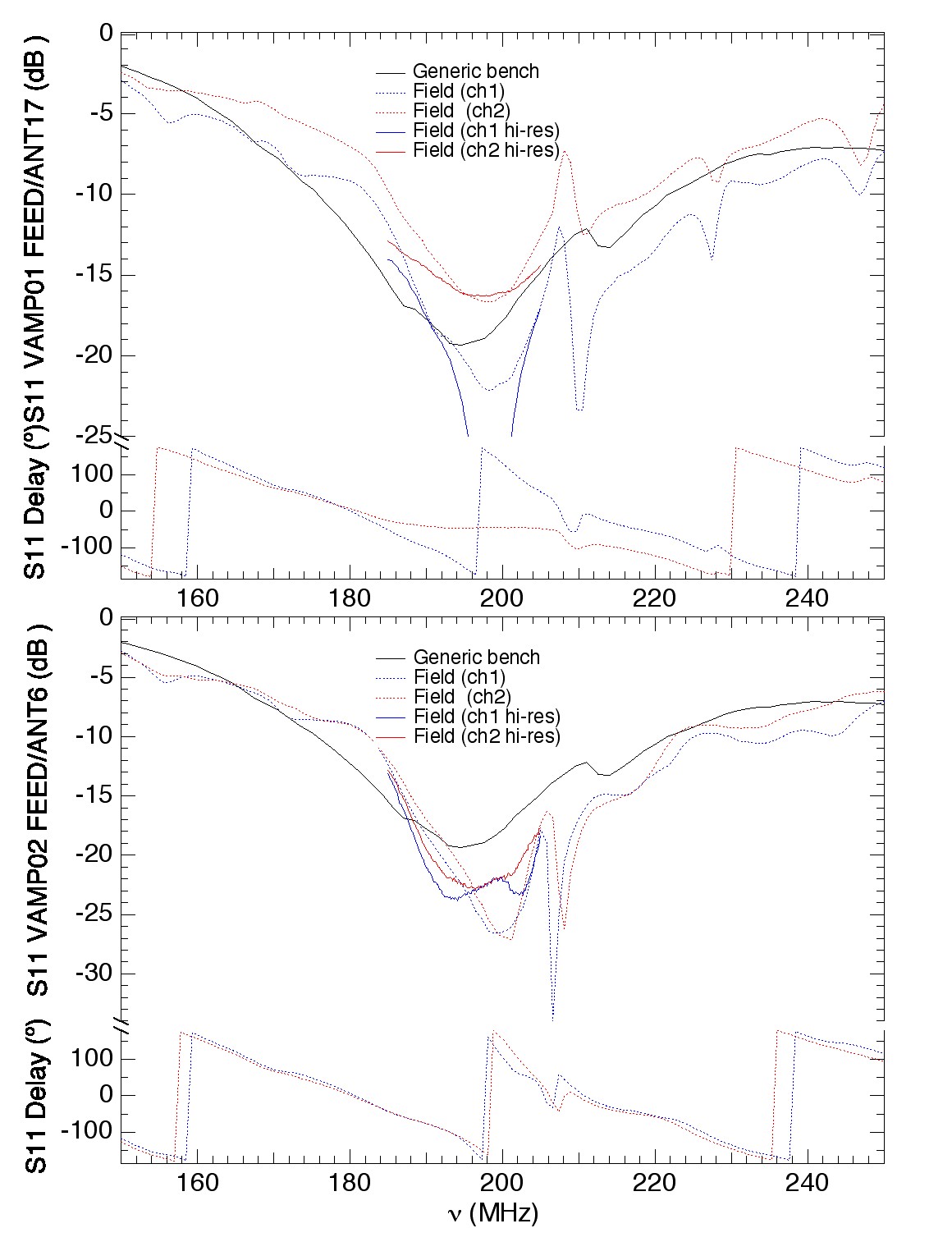
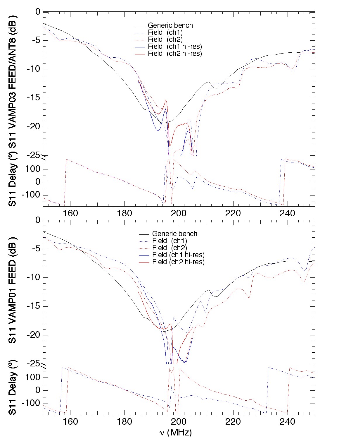
Impedance Match of Installed Feeds and Receivers (Prototype)
Reflection loss (S11) of feeds (ant 6, 17) w/r to
50 ohms showing reasonable narrow band results (Collins balun).
Reflection loss (S11) of feeds (ant 8, 26) w/r to
50 ohms showing reasonable narrow band results (Collins balun).
RFI Impact

Gain control levels with
and without 195.4/1.5 MHz
front-end filters, demon-
strating the effect of TV
carrier modulation. Unfil-
tered RFI destablizes IF
level control. |
 |
Gain control levels with
and without 191/14 MHz
front-end filters in
series
with 199.25 MHz low pass
filters (-20 dB). Exclusion
of ch 7 & 11 enable stable
level control. |
|
Gain control levels with
and without 191/14 MHz
front-end filters.
Exclusion
of ch 7 is sufficient to
enable stable level control.
|
Report
on impact of HSync pulse transmission from broadcasters
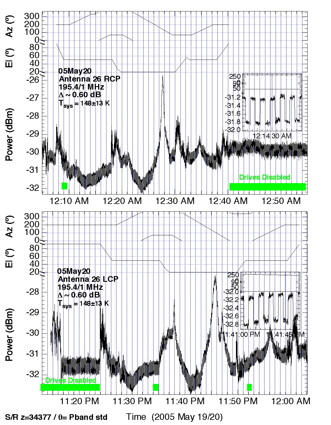
Tsys
Measurement of Ant 26 Tsys using the noise diode. Results nominal(05May20)
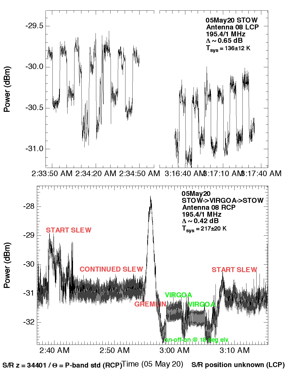
Measurement of Ant 8 Tsys using the noise diode. Results anomalous (05Jun03)
Measurement of Ant 8 Tsys using the noise diode. Results anomalous
(05May20)
Measurement of Ant 8 Tsys using the noise diode. Critical diagnostic
(1) inductive impedance of a 75 ohm transformer w/ terminated 50 ohm end,
(2) termination with a short (05May 18).
Lab characterization of VAMPS 03 and 04 noise & gain (ant 8, 26)
Lab characterization of VAMPS 03 and 04 Q - hybrid balance (ant 8, 26)
03/10/05 Bench performance of prototype receiver systems P1,
P203/12/05 Potential interference from FM broadcasting near
Riley, NM
| 2-band Holography Data Sets |
| Date |
Refant |
Target |
Source |
Size |
Oversamp |
Notes |
AIPS Slot |
Program |
| 28Jun |
26 |
8, 17 |
Cas |
25 |
4 |
prototype system
s/r rotn 45 deg |
2:14 |
RAP2F2 |
| 12Jul |
26 |
8, 17 |
Cas |
29 |
3 |
Ditto; s/r rotn 0 deg |
2:15 |
ACTST2 |
| 13Jul |
17 |
8, 26 |
Cas |
29 |
3 |
Ditto; s/r rotn 45 deg |
2:19 |
ACTST |
| 16Aug |
8 |
17, 26 |
Cas |
33 |
1.2 |
missing! Failed? |
|
RP2BND |
| 24Aug |
26 |
8, 17 |
3C123 |
35 |
1.2 |
prototype system |
2:34 |
RP2HOL |
| 11Nov |
26 |
8, 17 |
Cas |
15 |
3 |
shadowed; short dipole |
2:46 |
RAP3HO |
| 13Nov |
26 |
8, 17 |
Cas |
31 |
3 |
short dipole |
2:49 |
RAP3HO |
| 18Nov |
26 |
8, 17 |
3C123 |
25 |
3 |
TV on; long dipole |
2:46 |
AP2HOL |
| 30Nov |
26 |
8, 17 |
Tau A |
33 |
3 |
long dipole |
TBD |
ACTST |
| 23Dec |
26 |
8, 17 |
Cas A |
57 |
4; 4 cuts |
short dipole |
TBD |
ACTST |
| 28Dec |
8 |
17, 26 |
Tau A |
33 |
3 |
short dipole |
TBD |
ACTST |
| 2-band sensitivity data sets |
| Date |
Antenna |
Source |
Notes |
Mode |
BW (MHz) |
Program |
| 30Nov |
8, 17, 26 |
Tau A |
long dipole |
1A |
0.781 |
ACTST |
| |
|
|
|
2AC |
0.781 |
|
| |
|
|
|
1A |
1.56 |
|
| |
|
|
|
2AC |
1.56 |
|
| 13Nov |
8, 17, 26 |
3C123 |
short dipole |
2AC |
0.781 |
AP2BND |
| 11Nov |
8, 17, 26 |
3C123 |
short dipole |
PA |
1.56 |
AP3BND |
23Dec |
8, 17, 26 new RXs+feeds |
3C123 |
short dipole |
PA (obs every other band in sweep) |
0.781 |
ACTST |
28Dec |
8, 17, 26 new RXs+feeds |
3C147 |
short dipole |
PA |
0.195 |
ACTST |
| Table Notes: |
| Size means the number of points on each side of the grid. |
| Oversamp is the number of points per beam. |
| Slot shows the disk#:slotID# on OKANAGAN prior to
accidental Nov recat. |
| AIPS user on OKANAGAN is 196. |
| All data on disk for runs prior to 30Nov are calibrated. |
| NRAO archive unlock codes: |
| |
ACTST |
3UY5kdeK |
|
| |
ACTST2 |
MdncKbcL |
|
| |
RAP3HO |
Gu6RVBU2 |
|
| |
RAP2F2 |
6Se5qbjR |
|
| |
RP2BND |
ikJLcjHR |
(also known as RP002)
|
| |
RP2HOLd |
ditto |
(also known as RP002)
|
| |
AP2HOL |
public |
(also known as AP002)
|
| P-band Holography Data Sets |
| Date |
Refant |
Targets |
N |
Samp |
Source |
Note |
Slot |
Program |
| 02Mar2000 |
9,10,15 |
all other |
7 |
1.2 |
3C48 |
A focus test. I moved the Subr to see the effect. |
|
|
| 26Feb2000 |
9,10,15 |
all other |
34 |
1.5 |
3C147 |
|
|
| 21May2001 |
12,19,24 |
all other |
35 |
4.0 |
3C147 |
Some RFI in this run. |
|
|
| 29Jun2005 |
2,21,27 |
8,17,26 |
25 |
4.0 |
3C461 |
prototype loaded dipole on 8, 17, 26 rotn 45 deg |
1:91 |
RAP2P2 |
| 12Jul |
2,21,27 |
3,4,6,7,8,9,10,11,17,26 |
29 |
3.0 |
3C461 |
loaded dipole on 8, 17, 26 s/r rotn 0 deg |
1:90 |
ACTST
|
| 13Jul |
2,21,27 |
8,17,26 |
29 |
3.0 |
3C461 |
loaded dipole on 8, 17, 26 s/r rotn 45 deg |
1:92 |
ACTST
|
| 26Jul |
? |
|
? |
? |
3C147 |
A test file. |
1:97 |
|
| 26Jul |
6,9,12 |
8, 13,14,16,18,26 |
25 |
3.0 |
3C147 |
prototype shorted dipole on 17; loaded 8, 26 |
1:94 |
ACTST |
| 27Jul |
6,9,12 |
1,3,4,5,6,7,8,9,
11,12,15,17,21,
22,23,24,26,27 |
25 |
3.0 |
3C147 |
no prototype dipole on 8, 17, 26 |
1:96 |
ACTST |
| 16Aug |
2,21,27 |
8,13,14,16,17,26 |
33 |
1.2 |
3C48 |
prototype loaded dipole on 8, 17, 26 |
?? |
RPPBND |
| 24Aug |
2,21,27 |
8,13,14,16,17,26 |
35 |
1.2 |
3C123 |
prototype loaded dipole on 8, 17, 26 |
1:95 |
RPPHOL |
| 28Sep |
3,8,17,21,24,27 |
1,6,9,10,22,28 |
49 |
1.2 |
3C48 |
coordinates are wrong. |
1:05 |
|
| 22Oct |
3,8,24 |
4,12,13,14,16,18 |
45 |
1.2 |
3C461 |
prototype loaded dipole on 8, 17, 26 |
1:06 |
|
| 11Nov |
26 |
6,13,14,16,18,20 |
15 |
3.0 |
3C123 |
shorted short 1.5m dipole |
1:01 |
AP3HOL |
| 11Nov |
22,26,28 |
13,14,16,18,20 |
X37 |
3.0 |
3C123 |
filler for above. NO SHORT APPLIED. DATA BAD. |
1:02 |
APPHOL |
| 12Nov |
22,26,28 |
13,14,16,18,20 |
X37 |
3.0 |
3C144 |
filler for above. NO SHORT APPLIED. DATA BAD. |
1:03 |
APPHOL |
| 13Nov |
22,28 |
13,14,16,18,20 |
X37 |
3.0 |
3c147,3c196 |
filler for above. NO SHORT APPLIED. DATA BAD. |
1:04 |
APPHOL |
| *** The preceding four files form a single 37 x 37 raster with oversample = 3 *** |
| 17Nov |
4,15,24 |
2,6,8,10,11,17,22,26,27 |
21 |
3.0 |
3C84 |
shorted long 1.5m dipole, 400 msec dump |
1:89 |
APPHOL |
| 17Nov |
4,15,24 |
all minus 14, 16 |
57 |
4.0 |
3C48 |
two long cuts, not a raster |
2:01 |
APPHOL |
| 14Dec |
2, 3, 4, 21 |
all |
29 |
3.0 |
TauA |
shorted short 1.5m dipole. no last row. |
|
ACTST |
| 14Dec |
6, 9, 10 |
8, 17, 26 |
21 |
3.0 |
CasA |
shorted short 1.5m dipole. |
|
ACTST |
| P-band sensitivity data sets |
| Date |
Antennas |
Source |
Notes |
Mode |
BW (MHz) |
Program |
| 11Nov |
8, 17 (new feed), 26 (old feed) Old RXs |
3C123 |
shorted short dipole 300-345 MHz |
2AC use IF1 |
3.125 |
RAP2F2 |
| 17Nov |
8, 17 (new feed), 26 (old feed) Old RXs |
3C84 |
shorted long dipole 300-345 MHz |
2AC use IF1 |
3.125 |
AP002/APPHOL? |
| 14Dec |
8, 17 (new feed), 26 (old feed) Old RXs |
3C48 |
shorted short dipole 300-345 MHz. only line scans
in linked obs file used. |
2AC use IF1 |
3.125 |
ACTST |
| 23Dec |
3, 4, 27 (no 2-band) 8, 17 new RXs+feeds |
3C48 |
shorted short dipole 302-344 MHz. |
PA ant 8 may be xpolz; every other band in sweep |
1.56 |
ACTST |
| 28Dec |
6, 9, 10 (no 2-band) 8, 17 new RXs+feeds |
3C147 |
shorted short dipole 302-344 MHz. |
2AC |
0.195 |
ACTST |
| Table Notes on P-Band: |
| Size means the number of points on each side of the grid. |
| Oversamp is the number of points per beam. |
| Slot shows the disk#:slotID# on OKANAGAN for
calibrated data prior to accidental Nov recat. 2000-2001 data are on tape. |
| AIPS user on OKANAGAN is 327 |
| NRAO archive unlock codes: |
| |
ACTST |
3UY5kdeK |
|
| |
ACTST2 |
MdncKbcL |
|
| |
RAP3HO |
Gu6RVBU2 |
|
| |
RAP2F2 |
6Se5qbjR |
|
| |
RP2BND |
ikJLcjHR |
(also known as RP002)
|
| |
RP2HOLd |
ditto |
(also known as RP002)
|
| |
AP2HOL |
public |
(also known as AP002)
|
|
|
|


