Sasha's UVCS line-fitting IDL toolkit
(SULFIT) USER MANUAL
Revision 5.0
--
Introduction
o
Installation and start-up
o
Variables WS and L
--
Reading a FITS file(s)
--
Using SULFIT
--
Using DAS
--
Selecting slit region (optional)
--
Applying flat field (optional)
--
Selecting spectral line(s)
--
Fitting the line(s)
o
Fitting generic line(s)
o
Fitting Ly-alpha line
o
Fitting OVI line doublet (1032, 1037 Ang.)
--
Appendix A
--
Appendix B
--
Appendix C
Introduction
The IDL line-fitting toolkit (SULFIT) is created to automatically
perform routine actions that are required to get meaningful scientific values
from UVCS spectral line profile data. As of version 4, SULFIT performs the
following actions (mostly without user intervention):
--
Reads UVCS FITS file
--
Throws away bad exposures
--
Combines similarly configured
exposures
--
Performs radiometric & wavelength calibrations
--
Finds one line or several spectral
lines by their wavelength
--
Selects a ROI (region of interest)
on the detector image relevant to specified lines
--
Corrects instrument distortion
--
Sums detector rows to get a line
profile
--
Applies the detector effect
correction (reshapes the profile)
--
Estimates the intensity
distribution across spectrometer slit and models the effect of the spectrometer
on the line profile, taking into account the slit shape, instrument optical
width and detector digitization effect
--
Estimates errors of the model
fitting
--
Estimates the interplanetary
hydrogen contribution to Ly-alpha line
--
Estimates stray light contributions
to major lines and models the complicated stray light profile for Ly-alpha
line.
--
Fits line profile to the data
taking into account the instrument model, assuming that coronal emission can be
modeled by one or two Gaussian profiles.
(Note:
Several overlapping spectral lines can be fit simultaneously.)
--
Calculates physical values and
their errors from fit parameters, taking into account Poisson statistics,
uncertainties in the instrument specification and the fitting errors.
--
Presents the results
in a nice plot with an informative legend.
All of
the above functions can be achieved
quite easily by running only three IDL commands, like the following:
ws= comb_by_pattern('/SCI/d96.06.21.16:53:56.ovi.dat.gz')
l = get_line5(ws,0,[1032,1037])
fit_ovi4,l,/two
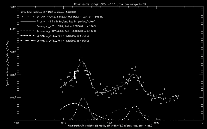
As an example, the
figure below shows a sample plot produced by running the above IDL commands.
Each
of the procedures in the toolkit allows the user to specify a number of
additional options to "tune-up" fitting to obtain an optimum
presentation of UVCS data. The most frequently used options are described in
following sections. See the following sections and the information in the
appendices to learn about all of the options.
Installation and
start-up
Most of the relevant fitting routings are included in
one file called SULFIT5_standalone.pro,
however there are additional routines needed from das51_standalone2.pro.
The
user should compile both files by using the following IDL commands:
.comp
das51_standalone2.pro
.comp
SULFIT5_standalone.pro
mn,/no_gui
Instead
of running these commands separately, they can be run by using the IDL batch
file command:
@sulfit
Variables WS and L
SULFIT uses variables of the same structure type as DAS 5.1 to
store FITS files information. They are represented by the variable WS in the text
below.
The user may use any variable
name as long as he does it consistently.
SULFIT uses variables of structure type, represented below as the
variable L, to store the line
profile data and all relevant information and pass them to other SULFIT
routines. The structure of this variable is described in Appendix A. Again, the user
can use a different name other than L.
Reading one or
more FITS files
Using SULFIT
To read a single file or set of files,
use the following:
WS = comb_by_pattern('filename pattern'[,more patterns.....])
where FILENAME PATTERN may include UNIX shell
wildcards, like '*" or '?'
This command can be used to merge multiple files together before
further processing.
It works only on
files with the same detector mask. The command removes bad exposures, does
the SPVL configuration (geometric) calibration and combines exposures with
similar mirror angles and grating positions.
Using the DAS
Users can use DAS version 5.1 to read one
or more FITS files and combine/delete exposures in any way (s)he
wants.
The FITS files should be
processed with the SPVL Configuration Calibration (but not the Wavelength Calibration) . It is preferable to leave exposures for several heights
in the single data set - SULFIT uses information from different heights to
obtain intensity profile across the slit. DAS stores data into variables named
WS0...WS9 according to the position in the DAS table. After the processing is
complete, the user should quit DAS and return to command line.
NOTE: Using the DAS to read the FITS files is
not well tested, so it is preferable to use SULFIT batch file to start the
process.
Selecting
spectral lines
To select spectral lines to be investigated, the user
calls the GET_LINE5 procedure like this:
L = get_line5(ws,exp,wl[,optional
keywords])
This function retrieves data for the
spectral lines with given wavelengths wl
(
in Angstroms) from exposure
exp
in working set ws.
It automatically selects the proper column range on the detector mask for the
given lines. Then the function integrates photon counts over the specified
region of the detector (see ROWS and COLS parameters description) and makes (by
default) distortion and detector effect corrections. You don't have to specify
precise wavelength for Lya or OVI ,
i.e., 1216,1032, or 1037 will do just fine. The L structure returned by this function
contains all information necessary to model and fit specified coronal line.
The parameter wl may be a vector of wavelengths (e.g. you
specify [1032,1037] to analyze the OVI doublet or even
[1026,1032,1037] if the lines are overlapping). All lines should be on the same
mask panel. User should be careful to avoid any unspecified line in the
selected region, since it will distort the fitting for the selected line(s). In
this case, the user should add the new line to wavelength selection.
See Appendix
B for the names and meanings of the other (optional) keywords.
Fitting the spectral
line(s) in the detector mask:
a) Fitting a generic spectral line
To fit one or more
generic lines, using one or two Gaussian profiles for each line, the procedure
FIT_ANY4 can be used as follows:
FIT_ANY4,L
The most frequently used keyword parameter
is shown below:
--
TWO - to fit each line
with two Gaussians instead of one
See Appendix
C for the names and meanings of the other (optional) keywords.
b) Fitting the Ly-alpha line
To fit Ly-alpha line,
the user should call the FIT_LYA4 procedure as follows:
FIT_LYA4,L
This function fits the Ly-alpha (1216 Ang.) line which has its
parameters described in the structure
L . L is returned by using the command: L=get_line5(ws,exp,1216). FIT_LYA4 can be used with the combination of one or two Gaussian
profiles, background correction, and optionally, the interplanetary hydrogen
and stray light profiles separated. The
output is an annotated plot showing the fits and fitting parameters for the
separate profile components.
Frequently used keywords for FIT_LYA4 are shown below:
--
TWO -to fit coronal
line with two Gaussians instead of one
--
IPH - to include the
interplanetary hydrogen profile when modeling the line profile
--
STRAY - to include a
stray light component when modeling the line profile
See Appendix
C for the names and meanings of the other (optional) keywords.
c) Fitting OVI line doublet (1032, 1037 Ang.)
To fit the OVI line
doublet, the user should use the FIT_OVI4 procedure as follows:
FIT_OVI4,L
L is the result returned by using the
command: L=GET_LINE5(ws,exp,[1032,1037][,optional
keywords]). FIT_OVI4 can be used with the combination
of one or two Gaussian profiles for each line, and background component. The output is an annotated plot showing the
fits and fitting parameters for each component. FIT_OVI4 has an additional feature not found in FIT_ANY4, in
that the fitting parameters can be restricted by using some physical
assumptions to improve fit. These assumptions are:
1.
The distances between the centers
of wide and narrow components are the same for both lines.
2.
The wide components and narrow
components are the same, correspondingly, for both OVI lines (this assumption
can be switched off by using the DIFF_WIDTH keyword. In principal, the corresponding widths for
the two OVI lines may be different, but not by more than about 5%, which is
usually well inside the error bars for the fits. When this option is *not* used, the output plot uses the word "TIED" for line
width for the second spectral line. This
means that the width is the same as for corresponding component in the first
spectral line.
Frequently used
keywords are:
--
TWO - to fit each line
with two Gaussians instead of one.
--
DIFF_WIDTH - to use
the same widths for the corresponding wide and narrow components of both lines
See Appendix
C for the names and meanings of the other (optional) keywords.
Appendix A
L is the structure
containing following fields:
--
WL=scalar (or vector)
wavelength(s) of spectral lines.
--
K=structure - copy of ws.k
--
F=structure - copy of ws.f(exp)
--
EXP=scalar - exposure
--
PANEL=scalar - mask
panel
--
LINE=vector - data
points of spectral intensity
--
FWHM=scalar -
instrument FWHM (pixels)
--
FWHM_RMS=scalar -
error in instrument FWHM (pixels)
--
REDUNDANT=boolean - whether line is in redundant area
--
SECOND=boolean - whether line is in second order
--
DP=structure -
detector parameters
--
WAVEL=vector -
wavelength corresponding to each data point
--
C_WAVE=structure -
copy of ws.c.<det>.wave
structure
--
GAUSS_C=vector -
parameters of Gaussian fit for every spectral line
[integral,1/width,center,background] AREA_OCC=scalar - effective mirror
area for each column ColsInPrevPanels=scalar - number
of detector columns in previous panels
--
Igradient=scalar - natural logarithm of the intensity gradient in corona
--
SLIT_WIDTH=scalar -
slit width
--
ROWS=[first,last] - vector of length 2 which specifies range of
the mask rows to integrate over. Whole mask by default.
--
COLS=[first,last]- vector of length 2 which specifies range of
the mask columns to integrate over. If not specified the procedure selects the
range automatically by fitting line to Gaussian and taking region of several
line widths around the line (see NUMOFSIGMAS parameter description).
--
NO_RECT_SLIT=boolean - avoid realistic slit modeling - can be used if
fit functions have trouble converging due to bad statistics
--
NODISTCORR=boolean - omit distortion
correction. (WARNING!!! Distortion
correction in "get_line" works by finding the
center of the line for every row of detector, fitting center vs row dependency to parabola and then shifting rows to put
all centers to the same column. It may be screwed up if CME is present or if
photon counts statistics is poor. Use /DIST_PLOT option to check (it is good
idea to always use it)).
Note: If you see an error
message like "CORRECT_DISTORTION3: Cannot correctly determine
distortion!" then statistics is too bad and you have to use this option.
Appendix B
The optional KEYWORDS for the IDL function GET_LINE5.pro:
ROWS=
[first,last] - vector of
length 2 which specifies the range of the mask rows to integrate over. It assumes ALL mask rows by default.
COLS=
[first,last] - vector of
length 2 which specifies the range of the mask columns to integrate over. If
not specified, the procedure selects the range automatically by fitting the line
to a gaussian and taking a region of several line widths
around the line (see the description for the NUMOFSIGMAS parameter).
DF=
dark field level array - if you have one you can specify it. (This is rarely
used.)
NOCORR= boolean - If
present, this omits the detector effect correction.
NODISTCORR= boolean - if
present, this omits the distortion correction.
(WARNING!!! Distortion correction in
"get_line5" works by finding the center of the line for every row of
detector, fitting the line center vs. row dependency to a parabola and then
shifting the rows to put all line centers in the same column. It may be
unreliable if a CME is present in the data or if the photon counting statistics
is poor. Use the /DIST_PLOT option
to check this (it is a good idea to always check). If you see an error message
like "CORRECT_DISTORTION3: Cannot correctly determine distortion!"
then the statistical uncertainty is too large and you have to use the
NODISTCORR option.
DIST_PLOT= boolean.
Plots the line center vs. row dependency for uncorrected data and then uses a
parabola for the distortion correction. This is useful to check how well the distortion
correction works since the correction allows large Doppler shifts.
EXT_PROF= vector. Use this if you
have your own zero-integral function to use for the detector effect correction.
Otherwise, the built-in function is used.
DIST_COEFFS= vector. The coefficients of the parabola, which is used to
correct the array distortion, are stored in this variable. Use this keyword if the
variable named "vector" is undefined (this can happen by using the IDL command
"delvar, vector" for example). If the vector
variable is defined, then it is used as the coefficients for the parabolic
correction and no new values are calculated.
NOFIND= boolean.
Use this to turn off the automatic routine for finding the spectral line.
Instead, the spectral line is specified with the COLS keyword. The use of the
NOFIND keyword is *not* recommended.
NO_RECT_SLIT= boolean.
Use this to turn of the realistic slit modeling (i.e. coronal intensity
variation with height across the slit).
This can be used when the fitting functions have trouble converging due to
poor statistics of the data to be fitted.
Appendix C
The optional KEYWORDS for the IDL
procedures FIT_ANY4.pro, FIT_LYA4.pro,
and FIT_OVI4.pro are shown below: (These keywords are passed to an IDL procedure
named FIT_ALL)
ADD_NAME= string - additional text to appear for the description of the
Y-axis
BAD_POINTS= vector - array indices for the points in the profile which are
considered to be "bad." When used, these points will not be used for the making
the fits. **NOTE: due to the negative
spectral dispersion in the OVI channel, the resulting plot is reflected along
the vertical axis. This must be taken into account when specifying the BAD_POINTS
relative to the original data (i.e. the array indices increase in the opposite
direction from the original data). The actual indices should correspond to
those in L.line.
NOPLOT= boolean -
no plot is displayed
LOG=
boolean - use a log plot for
the y-axis
DATA_ERRORS= vector - used when calculating the errors in the fitting parameters.
Normally, FIT_ALL considers the
errors for every data point to have Poison statistics plus a component due to
background variations. However, if you
would like to specify errors differently you are welcome to do it by using this
parameter. It has to be of the same length and units as the structure L.line.
Revision history
4.01 --
fixed missing INIT_SYN common block
definition
5.0 -- all IDL routines were put
into a single file