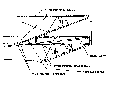
The purpose of the sunlight trap is to intercept direct solar
radiation which enters the entrance aperture, attenuate it, and
conduct and radiate the resulting heat to thermal radiators. A
diagram of the sunlight trap is provided in Figure 6  . It consists
of three cavities, two of which intercept the direct sunlight, and
a dark cavity between the others that is within the line-of-sight
of the spectrometer entrance slits. The dark cavity is shielded
from the direct solar rays by the central baffle (an extension of one of the trap walls) which has a knife edge at
its sunward end.
. It consists
of three cavities, two of which intercept the direct sunlight, and
a dark cavity between the others that is within the line-of-sight
of the spectrometer entrance slits. The dark cavity is shielded
from the direct solar rays by the central baffle (an extension of one of the trap walls) which has a knife edge at
its sunward end.
The cavities, which intercept the direct sunlight, are made of polished nickel
plated beryllium
with a specular black multilayer coating provided
by the Optical Filter Corporation.
Each cavity has two plates that intercept the solar
radiation. They are inclined at an angle of 20 .
.
The basic concept is to provide specular reflections with minimal scatter per bounce, a reflectivity of less than ten (three) percent per bounce in the uv (visible), and a minimum of seven bounces before specularly reflected sunlight leaves the trap. The surface finish is specified at 20 Å rms roughness to achieve an acceptable level of non-specular reflection.
Specular and non-specular reflectance measurements of
sample plates were performed at visible and uv wavelengths to ensure
acceptable performance. Specular reflectances at angles of incidence
between 10 and 70 were measured at 1216 Å, 1840 Å, 2537 Å, and
visible wavelengths. The results are more than sufficient to meet the
required reduction in irradiance between the trap and the spectrometer
entrance slit baffles of about 2x10
were measured at 1216 Å, 1840 Å, 2537 Å, and
visible wavelengths. The results are more than sufficient to meet the
required reduction in irradiance between the trap and the spectrometer
entrance slit baffles of about 2x10 for uv wavelengths and about
5x10
for uv wavelengths and about
5x10 for visible wavelengths.
In order to reduce the radiance of the dark cavity to acceptable levels, a secondary baffle prevents sunlight diffracted at the knife edge of the central baffle from entering the cavity, and the interior is coated with a non-specular black material.
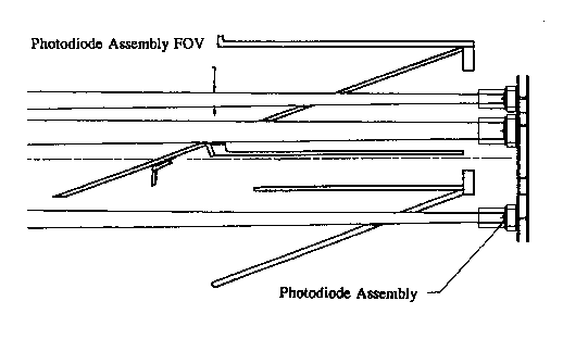
The sunlight trap includes four photodiode subassemblies that, together
with the entrance aperture, act as a fine Sun sensor (see Figure 7 ).
The photodiodes
are positioned to detect light at the edges of the direct sunlight beam.
The light level on the diodes depends on the locations of the shadow lines
from the edges of the entrance aperture. This information can be used
to determine the orientation of the occulted telescope system relative to
the Sun for a range of about  15 arc minutes. The instrument controller determines the orientation from the ratio of the difference to the sum of the light signals from photodiodes on opposite sides of the direct sunlight beam. Holes in the illuminated sunlight trap cavities
allow the sunlight to pass through the trap and onto the photodiodes.
A bandpass filter is located in front of each photodiode and a baffle tube
defines its FOV. The filter and
diodes are tilted so that the specularly reflected light will not
pass back through the holes in the cavities.
15 arc minutes. The instrument controller determines the orientation from the ratio of the difference to the sum of the light signals from photodiodes on opposite sides of the direct sunlight beam. Holes in the illuminated sunlight trap cavities
allow the sunlight to pass through the trap and onto the photodiodes.
A bandpass filter is located in front of each photodiode and a baffle tube
defines its FOV. The filter and
diodes are tilted so that the specularly reflected light will not
pass back through the holes in the cavities.