
MIRSI offers a large field of view (85 x 64 arcsec), diffraction-limited spatial resolution (0.8'' @ 10 microns at IRTF ), complete spectral coverage over the 8-14 microns and 17-26 microns atmospheric windows for both imaging and spectroscopy, and high sensitivity (20 and 100 mJy for a point source at 10 and 20 microns, respectively, for on-source integration time of 60 seconds) at IRTF . This system offers the unique ability to acquire both spectra and high-resolution, multi-wavelength images of an astrophysical source. This makes it possible to unambiguously correlate the spatial and spectral features observed in astrophysical sources and thereby reveal the key physical and chemical processes at work. MIRSI is uniquely suited to achieve our scientific goals, aimed at understanding young stellar objects and star formation, planetary and protoplanetary nebulae, starburst galaxies, and solar system objects such as planets, asteroids, and comets.
| Spectral Range | 2 - 28 microns |
| Pixel Scale (at IRTF) (diffraction-limited) | 0.27 arcsec/pixel |
| Field of View (at IRTF) | 85 x 64 arcsec |
| Spectral Resolution (imaging mode) | up to 1% bandwidth |
| Spectral Resolution (spectroscopic mode) | 200 @ 10 microns 100 @ 20 microns |
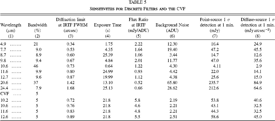
| Nominal point source sensitivity for 1-sigma detection in 60 sec. integration | 20 mJy @ 10 microns 100 mJy @ 20 microns |
| Optics | Reflective |
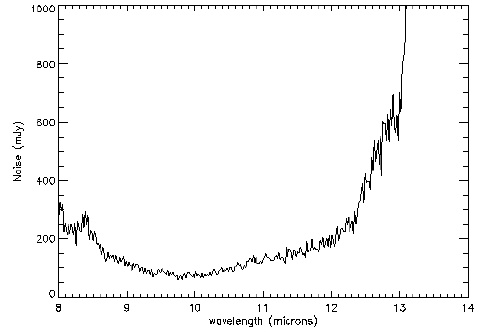
Below is a plot of the Grism sensitivity at 8-14 microns: (also available in: PS PDF formats). The sensitivity estimate is for 1 min. of on-source integration. The sensitivity is likely better, since because of telescope drifts, the FWHM of the standard star during the calibration did not always fill the slit.
My estimate is that an average one sigma is 150 mJy in one minute of on-source integration from 8-13 microns. The noise will decrease with the square of the exposure time. The noise quoted is per pixel. Pixels sizes along the slit are 0.265 arcsec on sky. The R=200 slit width is equal to the diffraction limit at 8.0 microns at the IRTF.
The MIRSI dewar design was developed, under our direction, at Infrared Laboratories, Inc. The dewar was designed to look upward - it attaches directly to the telescope at the Cassagrain focus in order to eliminate intermediate, warm optics from the optical path. The cold plate attached to the optics and the detector is cooled to LHe temperature. The optics chamber is surrounded by LHe- and LN2-temperature shields, as well as a floating shield to minimize heat load on the cryogens. Dewar thermal properties were designed to exceed a hold time of 30 hours. Internal structure design, while mainting low thermal conductance, ensures that mechanical flexure on the telescope results in a shift of only 1/10 pixel per hour of observation.
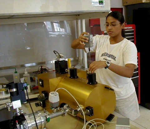
High school Honors intern Evelyn Aguilar measures cryogen levels in the MIRSI dewar
during vacuum pump out and thermal cool down. Optical
vacuum chamber and up-looking window (here covered by an aluminum dessicant trap) are
located in the box-shaped portion of the dewar.
Cryogen vessels and upward-facing fill ports for LHe (left) and LN2 are located in the
cylindrical extension.
| Filter Wavelength (microns) | Width (%) |
|---|---|
| 7.9 - 14.5 CVF | - |
| 4.9 | 21 |
| 7.8 | 9.0 |
| 8.7 | 8.9 |
| 9.8 | 9.4 |
| 10.3 | - |
| N-band 10.6 | 46 |
| 11.7 | 9.9 |
| 12.28 H2 | 1.5 |
| 12.3 | 9.6 |
| 18.4 | 8.0 |
| 20.6 | 37 |
| 24.8 | 7.9 |
| Grism Wavelength (microns) | Resolution | Slit Size ('') |
|---|---|---|
| 8 - 14 | 200 | 0.6 |
| 17 - 26 | 100 | 1.2 |
The two grisms cover 8 - 14 microns at a resolution of up to 200 (using a 0.6'' slit), and 17 - 26 microns range at a resolution of up to 100 (1.2'' slit). Filters for imaging consist of narrowband filters for both the 10 and 20 micron windows and a CVF operating from 7.9 - 14.5 microns (providing about 5% spectral resolution with our pupil size) to cover both feature and continuum wavelengths over the full spectral range of the instrument. Discrete filters include the stock mid-IR "silicate" set at 8.7, 9.8, 11.7, and 12.3 microns (~10% bandwidths), a filter for the 12.28 microns (1.5%) H2 emission line, and broad filters in N-band (10.6 microns, 46%) and 20.6 microns (37%). The hydrocarbon and fine-structure emission lines in the 10 micron window can be observed with the CVF. Also included are filters at 4.9 microns (21%), 24.8 microns (7.9%), and 18.4 microns (8%) filter. Plots of some of the MIRSI filter transmission curves are also available.
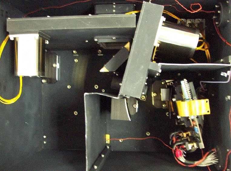
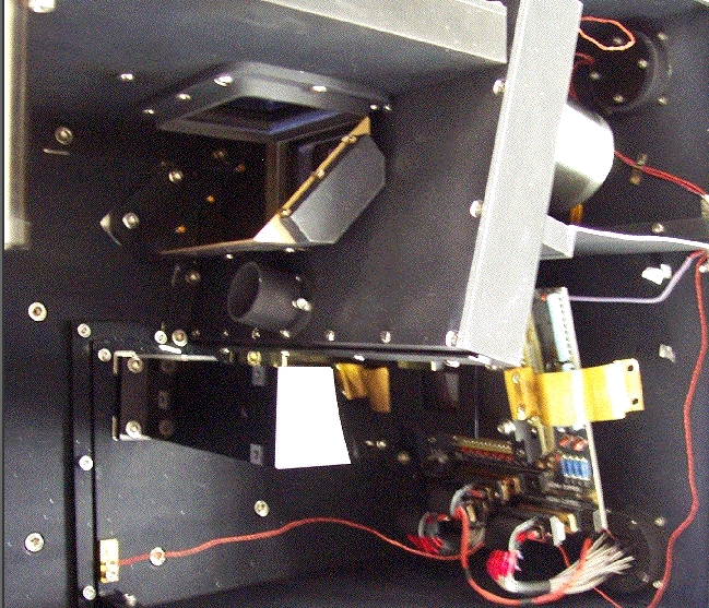
Views inside the optics box, with window looking upward.
Note aperture wheel housing (upper left), cryogenic motors,
filter wheel housing with pupil (middle box), and detector board (lower left).
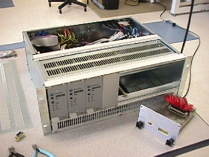
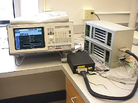
Cryogenic motor control and drives for MIRSI aperture wheel and filter wheels.
| Number of pixels | 320 x 240 |
| Pixel pitch | 50 microns |
| Material | Si:As |
| Technology | IBC |
| Operating temperature range | 6-12 K |
| Peak quantum efficiency | >= 45% |
| Dark current | <= 100 e- (T = 6K) |
| Frame rates | <= 1 kHz |
| Number of outputs | 16 |
| Well depth | >= 3 x 10^7 e- |
| Read noise | <= 1000 rms e- |
| Nonlinearity | <= 10% |
| Operability | 99% |
| Power dissipation | ~65 mW |