| Local Oscillator (LO) on the 1.2 m Millimeter-Wave Radio Telescope |
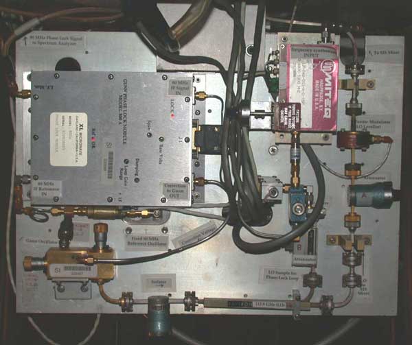
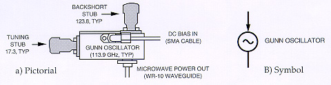
| The local oscillator power for the SIS mixer in the receiver is generated by a Gunn diode oscillator located on the LO plate mounted under the receiver. The Gunn oscillator is driven by a DC bias of 9-10 volts and is mechanically tuned to oscillate at a frequency from 78 to 118 GHz. At a given mechanical setting, the Gunn oscillator can be electrically tuned over a range of 700 MHz. |
| The local oscillator output frequency, which jitters over a range of several megahertz, is stabilized by a phase locked loop which holds the output frequency in a fixed (constant phase) relationship to a stable crystal-controlled oscillator. |
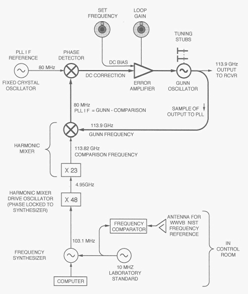
| The above figure shows the essential features of the local oscillator system, with the main loop drawn in heavy lines. In the main loop, a sample of the Gunn output is mixed with a comparison frequency to produce a difference frequency of 80 MHz. This signal (the PLL I F) is mixed in the phase detector with a fixed 80 MHz reference (PLL I F REF) to produce a DC output proportional to the relative phase of the two 80 MHz signals. When the two 80 MHz signals are in quadrature, the phase detector output is zero. As the relative phase shifts, a DC output is generated with a magnitude and sign proportional to the magnitude and direction of the phase shift. This error signal is amplified and added to the oscillator control voltage in order to correct the oscillator frequency enough to bring the 80 MHz signals back into quadrature. Because the PLL locks the Gunn oscillator output to a frequency 80 MHz above the comparison frequency, the Gunn frequency can be set by setting the comparison frequency. The comparison frequency is the 1080th harmonic of the basic reference oscillator. The basic reference oscillator is a frequency synthesizer with an output frequency set by the telescope control computer. The comparison frequency is generated in two steps. First, the harmonic mixer drive oscillator is phase locked to the 48th harmonic of the synthesizer output (this lights the H M DRIVE LOCKED LED). Second, this drive oscillator signal is applied to the harmonic mixer where its 23rd harmonic (the comparison frequency) is subtracted from the Gunn oscillator signal to produce the 80 MHz PLL I F.
|